History of Computer Art -- Part 2: Plotters
I’m writing a series of blog posts on computer art history from the 1960s onwards. In this installment we’ll talk about plotters.
This part can be read on it’s own, but for a quick introduction to the state of technology in the era, check out Part 1: Computer Graphics.
My personal fascination with plotters comes from watching it in action. If you look up media posts on Twitter for #plottertwitter, you will be rewarded with many delightfully hyponotic videos of plotters in action. As of early 2019, most of the plotters featured are modern, specifically the Axidraw by Evil Mad Scientist Labs. When I first saw them, I had assumed they were a cool new bit of tech, but plotters have had a long history going back at to least 60 years ago. While their capabilities have not varied much since their start, the ways in which they are used have shifted, most recently experiencing a re-emergence as within the generative art community.
What is a plotter?
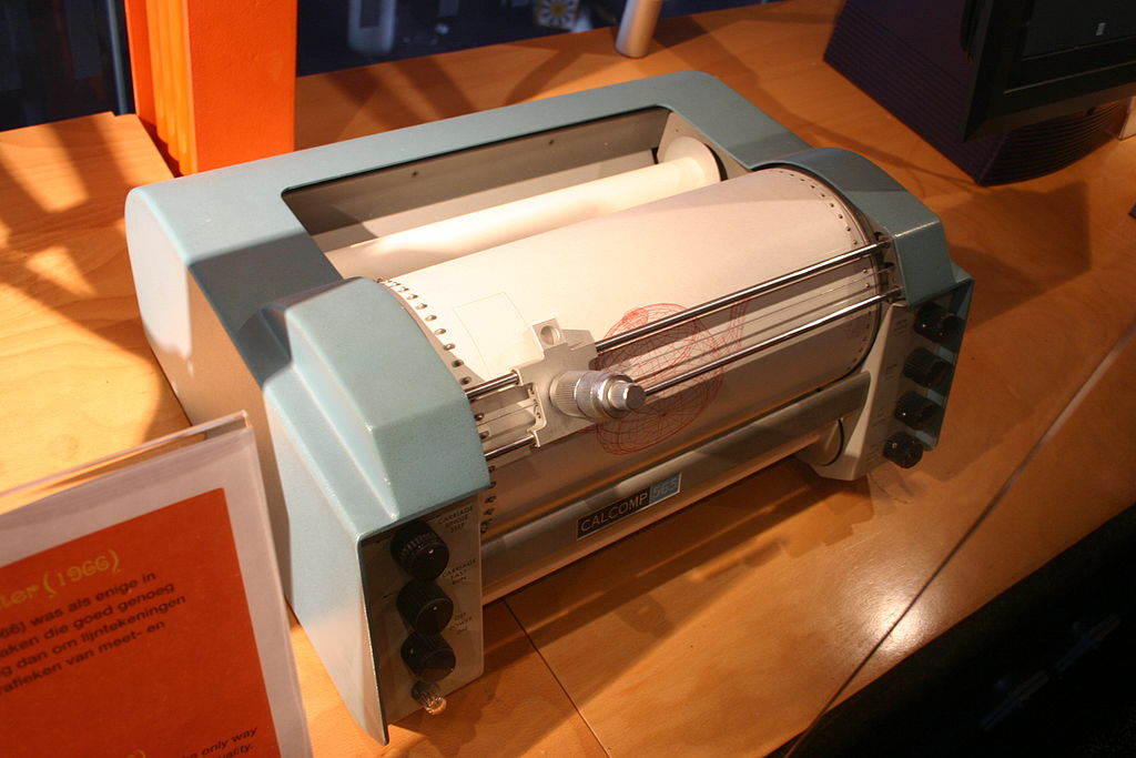 CalComp 565 plotter1
The first type of plotter was the mechanical plottter. I like to think of a mechanical plotter as a drawing robot. It holds a pen and can move accross a paper surface on a XY-axis. One of the earliest commercial plotters, the CalComp 565 was a drum plotter. To use it, you would load a roll of paper on which the machine could advance or reverse, moving on the Y-axis. The pen move across the surface of the paper and move on the X-axis. Drum printers such as the CalComp 565 allowed continuous rolls of paper to be fed into it, allowing up to 120 feet of continous surface, which made it ideal for large or continuous diagrams.
CalComp 565 drawing a sine wave 2
One of the premier manufacturers of plotters back in the day was CalComp, in Anaheim California. While researching this, I came accross one of their reference manuals which provided a nice overview of their available products in the 70s 1. CalComp ran from 1958 to 1999, when it closed due to lack of capital. But it seems like the company has been revived as a merger of two companies since and continues to produce large format printers and cutters.3 I’ll be using examples of their devices to illustrate the varieties of plotters available. I should note that CalComp wasn’t the only one to produce plotters then, other notable brands I came across when browsing were Benson, Hewlett-Packard (HP), and GRAPHOMAT.
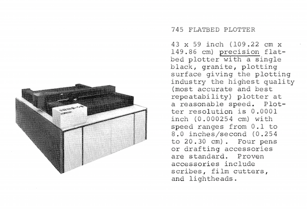 CalComp 745 Flatbed Plotter from a catalog 4
Another variety were the flatbed plotters. As the name suggests, the surface to be drawn on would be laid out flat, rather than rolled up on a drum. This was a preferred type of plotter for cases where you needed to view the whole piece as it is being plotted in real time, or if you needed to plot on various surfaces or paper that could not be loaded into a drum 1. Flatbeds also made it easy to update drawings by going over them in multiple passes, where I imagine it would be a nightmare to align if it were in a drum plotter. The Axidraw, for example, is a modern-day flatbed plotter.
And then they were the electronic or microfilm plotters. It works in a similar way as the mechanical plotter, but instead of a pen, it uses an electron beam and instead of paper, it “draws” on microfilm. The idea is that it plots an electron beam in a cathode ray tube, runs it through a camera lens system, which records these beams onto microfilm. I think of it like how a CRT display works, but it also exposes light onto film. The microfilm can then be viewed via a microfilm reader, printed or even animated.
A particularly notable microfilm plotter was the SC-4020, which was a peripheral device to the IBM 7090/7094. There is a whole book written on the SC-4020 and it’s use at Bell Labs in the 60s and 70s: Peripheral Vision Bell Labs, the S-C 4020, and the Origins of Computer Art by Zabet Patterson (MITPress link). It’s a good read and captures the zeitgeist of computer graphics at the time and I’d totally recommend it for further reading.
The first known computer animation was created by the SC-4020. It was titled “Simulation of a Two-Gyro Gravity Gradient Attitude Control System” by E. E. Zajac, 19635
The microfilm plotter had a special place in Bell Labs and was used in a number of creative applications in collaboration with their engineers and artists in residence. I’d recommend checking out Peripheral Vision if you’re interested in this. I’ll be leaving out microfilm plotters for this article as it is it’s own topic to be explored in a future post.
Analogous devices to the plotters that are still in use today are CNC machines, laser cutters and 3D printers. It is also interesting to note is that the term “plotter” is still used today to refer to large format printers, though now they work with inkjet or toner-based mechanisms.6
Applications
Historically, plotters were made with practical applications in mind e.g. drafting blueprints, graphing data, or drawing large format maps, all of which would be tedious to do by hand. But just like their computer counterparts, engineers and artists alike soon found creative applications for them.
In this promotional video for CalComp plotters in 1968, some applications that they mention are meteorology, atomic physics, medical research, oceanography, astronomy and so on.
In 1968, CalComp held an international plotter art competition. As part of the press release, I found this quote by James Pyle, assistant to the President at CalComp,7
"Pyle is convinced that computer/plotter art will be accepted as a recognized art form, "if only because it gives a humanizing aura to machinery."
I found the above interesting because it implied that computers at the time were found to be cold and inaccessible. Some 50 years on, computers are such a common fixture of everyday life and yet we continue to be fascinated by instances of computers doing “humanlike” things, e.g. robots that can can respond in conversation, traverse mazes, and most notably of late, this surge of interest in AI-created art.
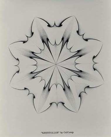
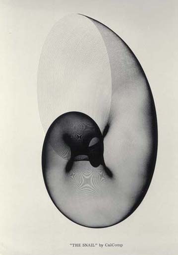 Select works from an exhibition announcing the CalComp art competition 8. The works were not credited, but one on the left is titled ‘The Snail’ and has been reproduced in other literature attributed to Kerry Strand.9
The press release for the competition most notably framed computer/plotter art as products of a collaboration between computers, a plotter and of course, human beings.
Drawing with machines
A defining feature of the mechanical pen plotter is the high resolution that it can draw. Some of the more premium CalComp models can draw on a resolution as fine as 0.0125mm. Plotters allowed for finer details that could not be captured via microfilm nor CRT displays at the time.
The Axidraw V3 plotter at work. Video my own.
Most plotter drawings of the early 60s and well into the 70s consist of black and white drawings consisting of fine lines. At first glance, this may not look very interesting or note-worthy, but there are certain features to plotter artwork that I find really compelling, beyond the fact that these were probably written in FORTRAN on punch cards, a feat that seems unthinkable today.
Because the plotter “prints” by moving a pen across a surface, drawings are defined as vectors, instead of a raster graphic. Raster graphics, which we more commonly use today represents an image by a rectangular grid of pixels, which printers can produce pixel by pixel. Some formats are GIF, JPEG and PNG. On the other hand, vector graphics represent images as a set of paths that draw lines and curves. SVG is a good example of a vector graphic format.
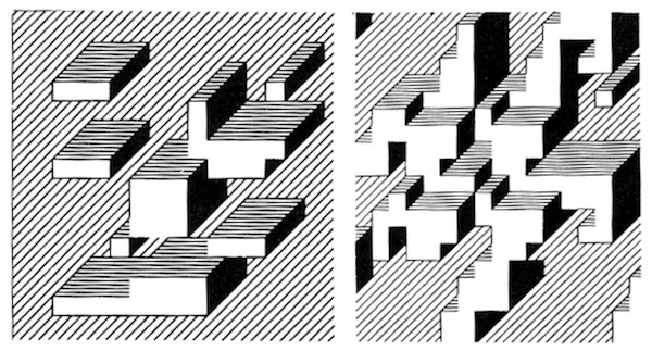
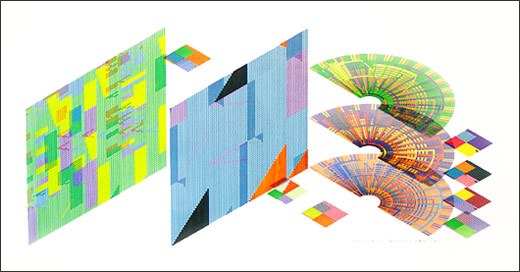
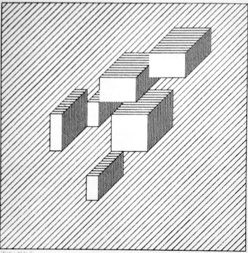 two images on left: select works from The Cube: Theme and Variation Series by Edward Zajec 10
right: a plot of similar theme titled RAM 13 also by Edward Zajec, 196911
two images on left: select works from The Cube: Theme and Variation Series by Edward Zajec 10
right: a plot of similar theme titled RAM 13 also by Edward Zajec, 196911
Working with vector graphics poses several interesting limitations, requiring a slightly different way to approaching a drawing meant for a screen. For example, look the above 1969 plotter piece by Edward Zajec titled RAM 1311. The title of the work, “RAM” comes from the name of the Random Number Generator (RAM) subroutine. This image was produced with a DP-1 Plotter run on an IBM 1620, written in FORTRAN IV, the programming language that shipped with it.
There are two major components to this image: the vertical lined background, and the grid of trapeziums in the background. To recreate this using my usual canvas-based drawing tools (like p5.js), the easiest way is to draw the background and to lay the foreground rectangles over it with a white fill. However, with a plotter, we need a way to tell the plotter to stop drawing those vertical lines where the rectangles exist. I started a discussion on Twitter on how to approach this which resulted in many interesting approaches. I was informed by a friend, David Lu that this was achievable using ray-casting to empty out the lined background from the foreground rectangles.
Because plotters are really good at drawing repeated fine lines (a feat that would be tiring to do by hand) it lent itself well to creating optical art (op art). A lot of op art features repetitive patterns that induce the illusion of movement on a static image. It is also worth noting that this overlapped with a rising interest in the aesthetic, marked by a wildly popular op art exhibit titled The Responsive Eye in 1965 held by the Museum of Modern Art in New York City.
A popular technique that surfaced a lot among plotter artists was the moiré effect. This can be achieved by layering two sets of fine-lined patters and offsetting them slightly.
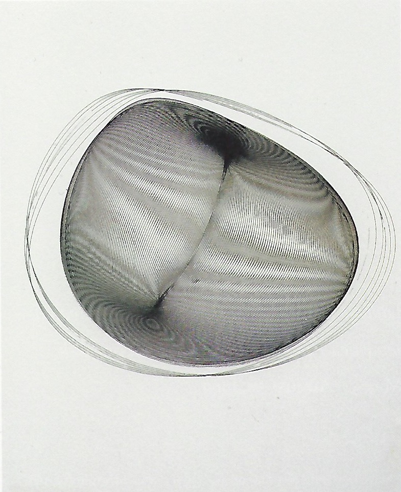
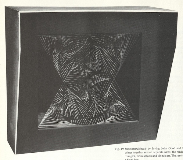 left: Mechano Drawing by Zoran Radović 12. right: Dioximoirékinesis by Irving John Good and Martine Vite 13
Radović’s work above (left) demonstrates the use of fine lines to create a moiré patttern. I also want to point out that it is not immediately clear if this was a plotter drawing from the description, but from the line quality and consistency it seems likely, or if not, a similar effect would be achievable by one. Next to it is a kinetic sculture that overlaid two fine line patterns, the idea of which was to create a “pulsing figure” in the black box by way of moiré effects.
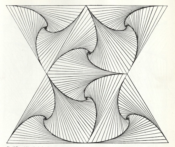
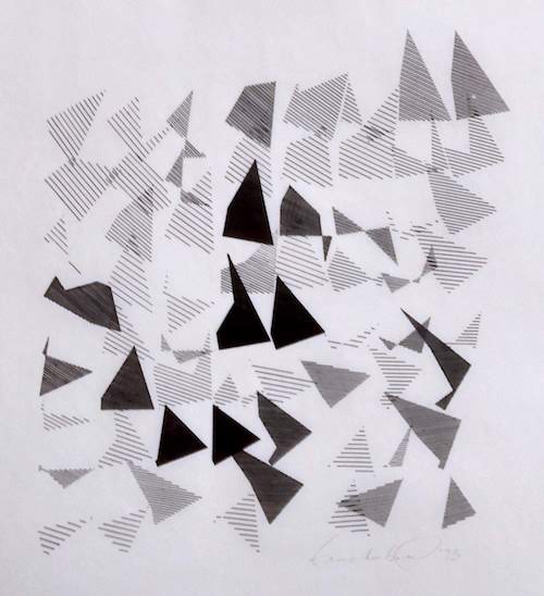
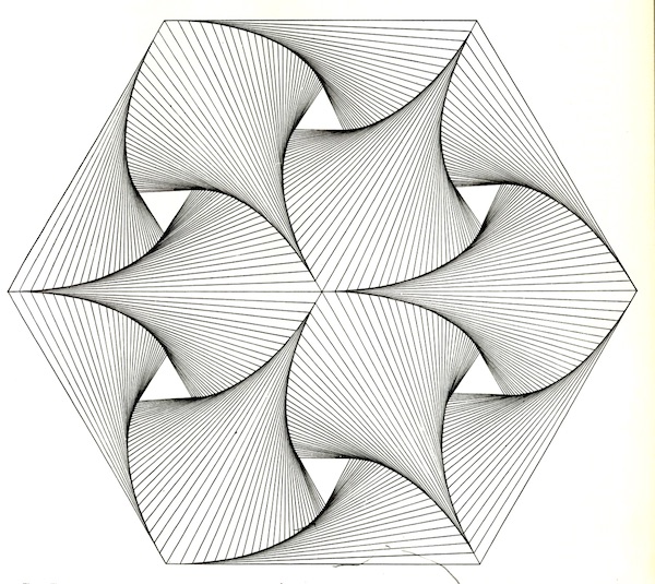 Computer-generated images by Irving John Good demonstrating a “vanishing triangle”10
I’ve also seen various applications of emerging patterns, such as the above. It was produced by tiling and nesting regular geometric shapes such as triangles that create an unexpected spade motif. This above one in particular also happens to be a visualization of a variation of the “four bugs problem” from calculus. As discussed in the previous article, a lot of early computer art was made by mathematicians and engineers and so it is little surprise that they take on patterns rooted from their respective fields of interest.
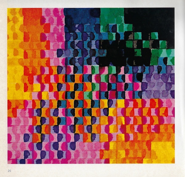 Matrix Multiplication by Frieder Nake, 1967. This visualization of a mathematical process was plotted using a GRAPHOMAT plotter 14.
 SkewR34 by Mark Wilson, 1983. This piece is a little more recent, but I decided to showcase it as an example of a piece that both demonstrates the use of fine lines and multiple colors.
It’s worthy to note that other output devices of the era such as microfilm and printers are often monotone, only available in black and white. Many microfilm works with color were often achieved manually by hand using colored filters, a manual process. On the other hand, plotters could hold up to four different pen colors or had pen holders that could be fitted various writing instruments. This allowed for textures and color density to be achieved by layering lines or by using different types of pens.
 Coded Algorithmic Drawing (#9) by Joan Truckenbord, 1975 as seen at the Whitney Museum of Art Note the use of varying line density to create different shades of color. This drawing was generated with FORTRAN and drawn by a CalComp plotter. Photo mine.
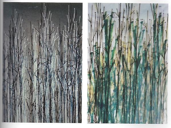 The Field by Grace C. Hertlein 15
This piece by Hertlein above demonstrates the use of multiple writing instruments and layers to create texture. The variation in colors and textures in The Field were achieved with the use of inks and nylon brushes that Hertlein could fit into a Calcomp plotter. Also not as obvious here is the appeal of the unpredictability of plotter art. The beauty of working with physical medium is that it sometimes has it’s own mind. The final result is subject to so many factors like the quality of your paper, the humidity in the air, your pen running out of ink, and so on. Hertlein may or may not have intended for the effet of the marker pens blending together here, but it adds depth that may not have been possible with other means of output. A similar effect could also be seen in Nake’s Matrix Multiplication as the marker pens bleed onto one another, creating a watercolor-like effect.
It is also worth noting that Hertlein was a the editor of the Computer Graphics and Art newsletter that ran from 1976 to 1978, a great resource on the more mature years of early computer art. PDF scans of the newsletter can be found on The Recode Project.
Why are plotters still so fascinating?
Why is it that we are still fascinated by this old-school drawing robot?
Everyone I know who has seen a plotter at work has absolutely loved watching it. I’m wondering if it’s just the pure novelty of it – most of us born after the 1960s probably have not encountered a plotter in our everyday lives. As a matter of fact, a finalist of a creative award in 2015 featured plotter work not unlike the ones from 50 years ago.
I think part of the novelty comes from the fact that our default output device is the color LCD screen and we have come to rely on other forms of output less and less. Some 15 years ago when I was still in high school, paper via printers (dot-matrix and laser) was still really my default mode of output. But now we have tablets, e-ink readers, phones, and so on. The need to manifest information on paper has been greatly minimized. It’s easy to forget that there was once a time when there wasn’t a prevalent graphics option where color and detail wasn’t so readily available.
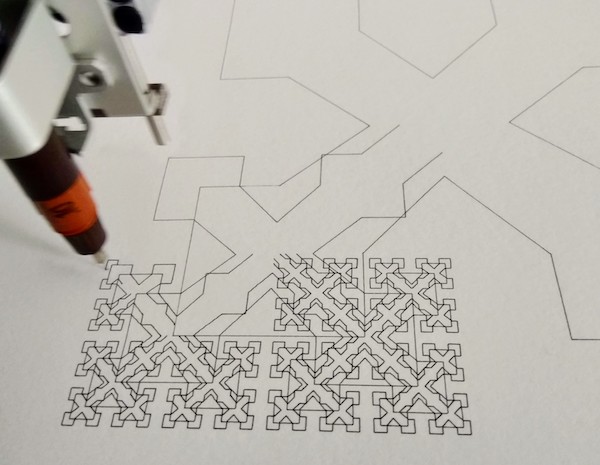 Photo is my own. The drawing being plotted is a recreation of “Stained Glass Windows”, the second place winner of a computer art contest in 1963, submitted by the US Army Ballistic Research Lab.
I like how plotters also offer a glimpse into the construction of its image. It paints, an image stroke by stroke, a single line at a time and it is satisfying to watch it come to fruitation. Much like how watching craft or cooking videos is so satisfying because you get to witness the birth of a delightful thing.
Perhaps as digital graphics are getting more and more sophisticated and complex, there is a certain comfort in looking at something two-dimensional in black and white. There is appeal in looking at a piece of generated art, trying to reverse engineer how it was created.
At any rate, there is a magical feeling you get when when you watch a little robot make you a physical piece of art. Watching a machine do something that is familiar to the human hand, working with familiar materials like ink and paper really humanizes it. Pyle was not wrong about the future of computer and plotter art – it still continues to fascinate us 50 years on.
Author’s note: Coming up next will be Part 3: Oscilloscopes and CRT displays where we explore some of the earliest ever ‘computer’ art from the 50s and grandparents of modern day display screens. Subscribe to my RSS feed to be informed when it gets published!
-
CalComp Software Reference Manual (1976). Retrieved from http://bitsavers.informatik.uni-stuttgart.de/pdf/calcomp/CalComp_Software_Reference_Manual_Oct76.pdf ↩ ↩2 ↩3
-
Hachtmann, P. (2007, Jun 9). CalComp 565 Plotter working. Retrieved from Youtube ↩
-
About Us on the CalComp Graphics Solution Website (2017). Retrieved from http://www.calcompgs.com/About ↩
-
Kammerer-Luka, G. F. (1976) Graphics Applications in the environment in Computer Graphics and Art for August 1976. Retrieved from The Recode Project ↩
-
Zajac, E. E. (1963). Simulation of a Two-Gyro Gravity Gradient Attitude Control System. Retrieved from Youtube ↩
-
Mott, E. (n.d.) Plotter Vs. Wide Format Printer. Retrieved from https://smallbusiness.chron.com/plotter-vs-wide-format-printer-58737.html ↩
-
Smithsonian Science Service High Resolution Exhibit Pictures. Retrieved from https://web.archive.org/web/20060903020302/http://scienceservice.si.edu/exhibit2.htm ↩
-
Smithsonian Science Service High Resolution Exhibit Pictures. Retrieved from https://web.archive.org/web/20060902234956/http://scienceservice.si.edu/8small.htm ↩
-
Strand K. (1964) Snail, [Computer generated drawing, black ink on Mylar]. From A Little-Known Story about a Movement, a Magazine, and the Computer’s Arrival in Art by Margit Rosen, 2011 (pp. 392) ↩
-
Good, I. J. and Vite, M. (1968) Science in the flesh in Cybernetics, Arts and Ideas by Reichardt, J., 1971 (pp. 100) ↩ ↩2
-
Fig. 2, Zajac E. (1969) RAM 13, [Computer generated drawing]. From A Little-Known Story about a Movement, a Magazine, and the Computer’s Arrival in Art by Margit Rosen, 2011 (pp. 392) ↩ ↩2
-
Radović Z. (1969) Mechano Drawing [Computer generated drawing]. From A Little-Known Story about a Movement, a Magazine, and the Computer’s Arrival in Art by Margit Rosen, 2011 (pp. 359) ↩
-
Good, I. J. and Vite, M. (1968) Dioximoirékinesis. From Cybernetics, Arts and Ideas by Reichardt, J., 1971 (pp. 106) ↩
-
Nake, F. (1967) Matrix Multiplication [Computer generated drawing]. From Computer Graphics Computer Art by Franke H.W., 1971 (pp. 27) ↩
-
Hertlein G. C. (1970) The Field [Computer generated drawing]. From A Little-Known Story about a Movement, a Magazine, and the Computer’s Arrival in Art by Margit Rosen, 2011 (pp. 493) ↩